First some terminology. The Top Pull-down Motor Assembly (TPMA) breaks down into four major sub-assemblies;
All the parts above and the gearnut discussed later are still available except the LM. The LM is only available through aftermarket sources.
The likely symptom you are experiencing with your TPMA is, it's in the down position (holding the top down) and it won't go up, or its in the up postion (top released) but it won't activate and pull the top down. These can be caused by a bad or dirty EM, a non-functioning RS, a cracked CPH, or a stripped gearnut (found inside the CPH).
The EM can easily be tested with an external 12v source. The CPH can be checked by eye-balling it for serious cracking The gearnut can be checked visually by disassemblying the entire TPMA and seeing if it is stripped. The RS can be checked with an VOHM. All these task are fairly easy to perform with the correct tools and a little mechanical ability.
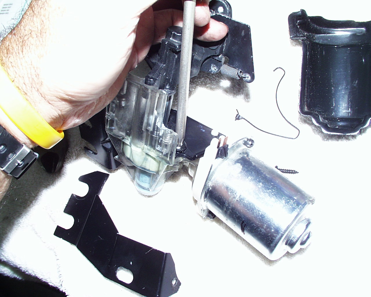
One diagnostic test is to attach one end of an alligator clip to a good ground source and the other end to the shaft of a screwdriver. Now place the shaft of the screwdriver into the LM simulating the j-hook's (found hanging from the top) latching action. If the motor draws the LM down there is a problem with top (the j-hook) being grounded. Retry the same test again only connecting moving the alligator clip from the good ground source to the j-hook.
In the first test above, if the motor runs but the LM doesn't go down you've learned two things: The motor is fine and either the gearnut is stripped or the CPH is cracked.
If in the tests above nothing happens (ie. the latch doesn't pull down the screwdriver shaft then its possible no power is reaching the motor, or the RS is bad.
To check power to the TPMA use an VOHM to verify you see 12v when touching the red probe to the TPMA and the black probe to a good ground (or the J-hook).
The next easiest diagnostic is to visually examine all sides of the CPH for serious cracking or distortion. This is done by first unpluggin the power socket from the passenger side of the TPMA then removing the two 13mm nuts and the one 10mm nut securing the TPMA to the car. Once removed you can easily manipulate the assembly around to see if there is any severe cracking in the CPH. If cracking is found then it needs to be replaced. The part # is 20160581.
The next easiest diagnostic is testing the EM. You'll need to remove the TPMA from the car for this test. See the pictures below for a guide.
Once removed, remove the RS by unscrewing the T15 torx screw and lifting the locking tab holding it to the EM housing while pulling it away from the LM & EM (see pictures below).
Next remove the two T27 torx screws holding the LM to the housing (see below).
Also remove the three 7mm silver nuts holding the adjusting plate to the CPH (see below).
Now as you pull the LM away from the CPH you should be able to separate the EM screw from the gearnut and CPH.
At this point you can visually check the gearnut to see if its stripped. With your fingers you can check if rotates freely as well. If its stripped order part no. 20160587. With the EM now on the bench and separated from the CHP simply touch 12v to one copper terminal and negative to the other. Note the direction it turns. Now reverse your connections, the motor should turn in the reverse direction. If it doesn't turn no matter which way you connect to power, you have a bad motor or dirty comutator and brushes. Only an expert should attempt this next step; that is cleaning the EM comutator and brushes. If the EM works after cleaning you saved yourself from buying a new one, part no. 16608837. Disassemble the EM by unscrewing the two phillips screws and pulling the case and comutator-screw shaft away from the brushes housing. Of course the brushes will fall out of position and will take some ingenuity to figure out how to hold them in place during re-assembly. Remember, if you aren't an expert at working on electric motors and re-assembling them you probably should not try this as you may never be able to put the motor back together without a LOT of frustrating trial and error. The trick to reassembling the motor after the comutator has been removed is to first remove all pressure caused by the brushes springs by cocking them in a no-pressure configuration. This is so you can slip the comutator in place. Then while holding it in place un-cock the springs which will re-apply spring tension on the brushes pushing them firmly against the comutator.Now while holding the comutator in place (I used a 6" piece of string wrapped around the comutator. One could probably use a vise grip on the shaft screw), slide the silver housing over motor windings (pull the string out) then reattach the silver housing using the two phillips screws.
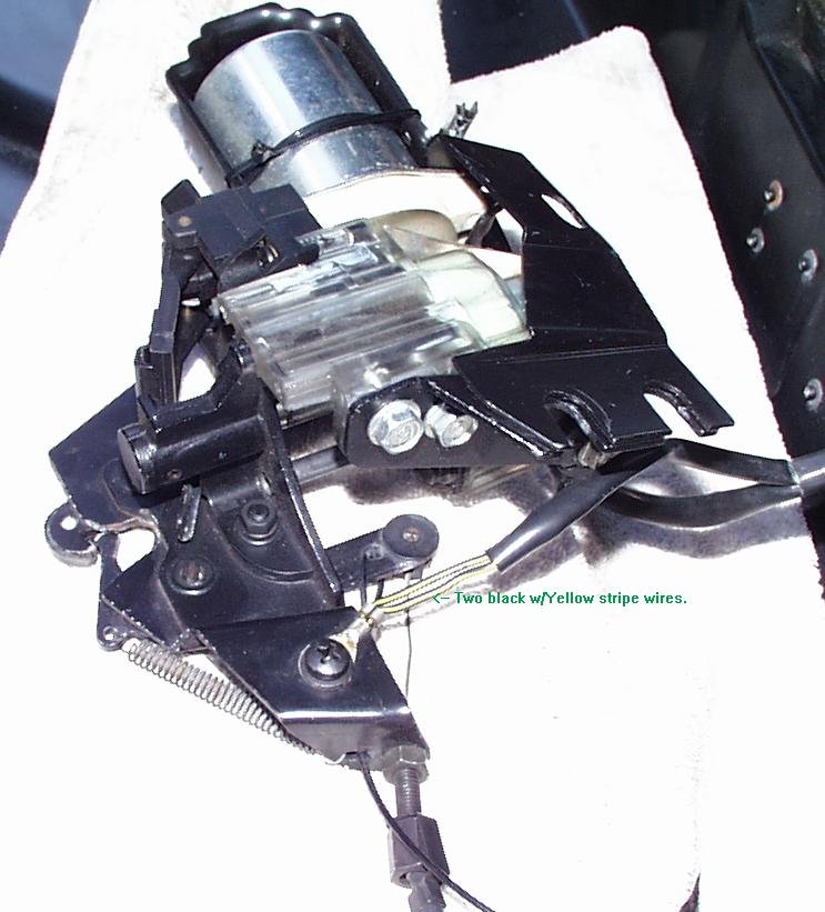
Hopefully at this point you have solved your problem (ie. the motor works). Lets test everything to find out. If the CPH isn't cracked and the gearnut isn't stripped and the EM runs with 12v applied then the RS is the likely culprit. Part no. 16629927 (see note at bottom of this page). The RS has two moving components. The broad rectangular flat surface with a metal lever riveted to it. and beneath the surface a "click" or toggle switch. The "click" switch must be in the down position when you reverse the motor to drive the LM up. Also, remember when its in the down position make sure you put/hold the switch's flat surface down with your finger as well.What follows are some motor drawings and disassembly photos that might be helpful to you should you want to attempt repair yourself. Good luck!
Drawing from Allante Parts & Illustration Guide
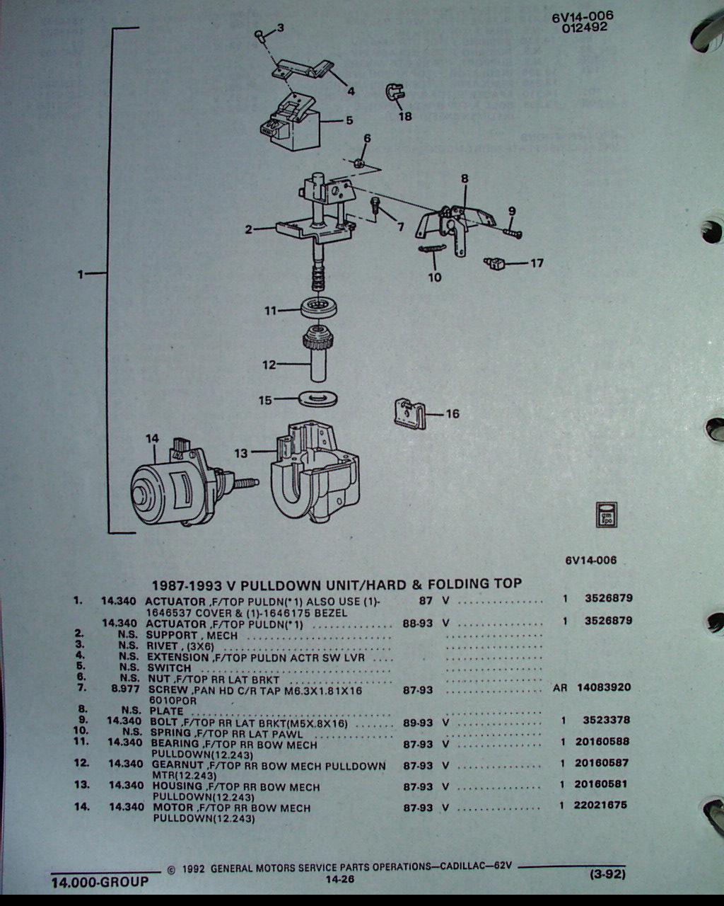
Drawing and key part numbers from GM Parts Guide

Tools used.
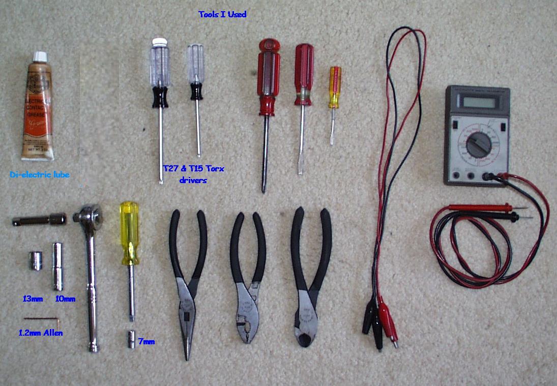
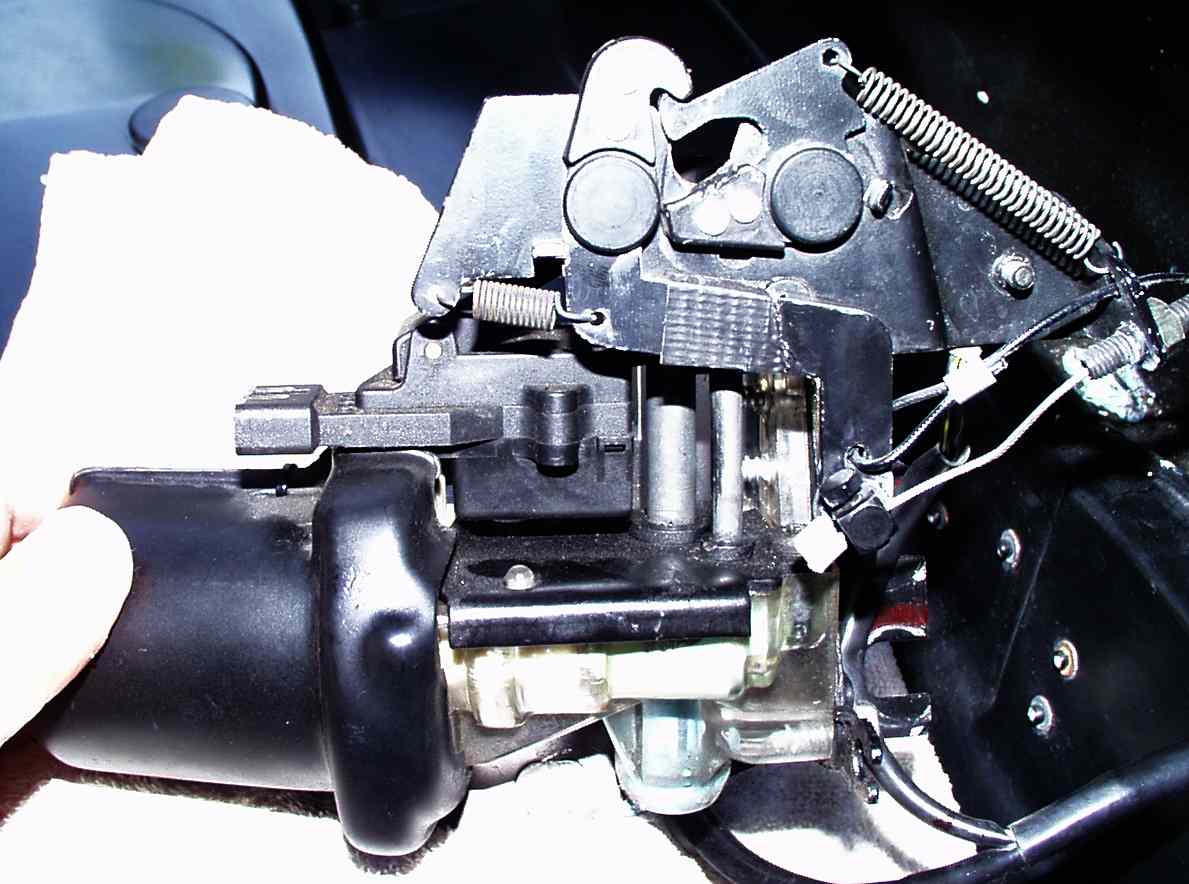
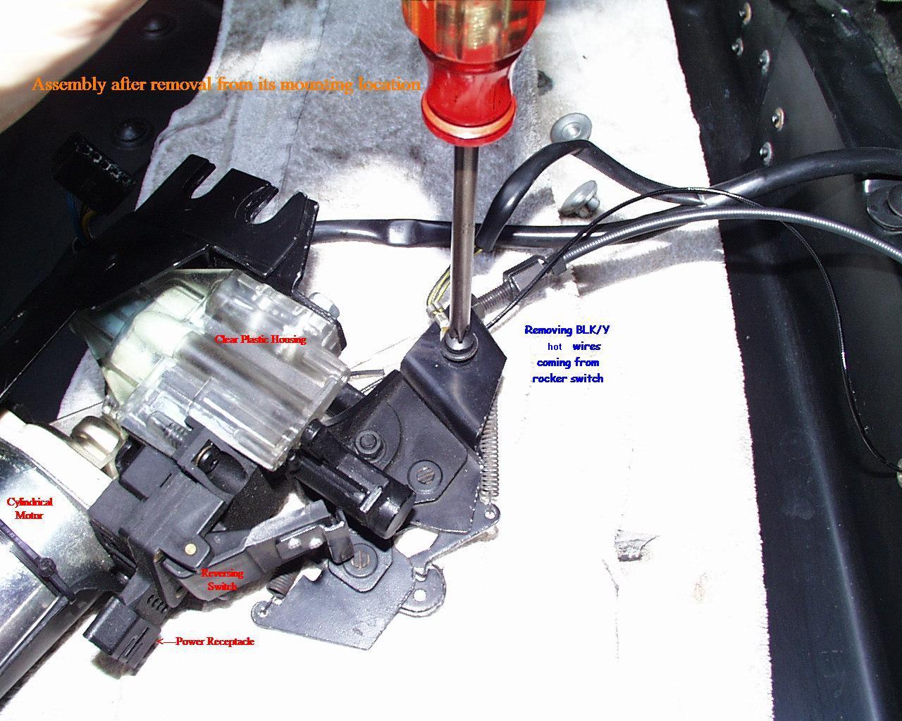
Photo of full assembly with key parts annotated
You must remove, Wire crimp (A) and loosen set screw (B) and clip (C) then pull
cable (D) from path.

Removing crimp (A). Set screw seen just to right of crimp.

Removing set screw w/1.2mm allen

Spreading tabs of clamp apart

Pushing Manual Release wire from trunk through grommet

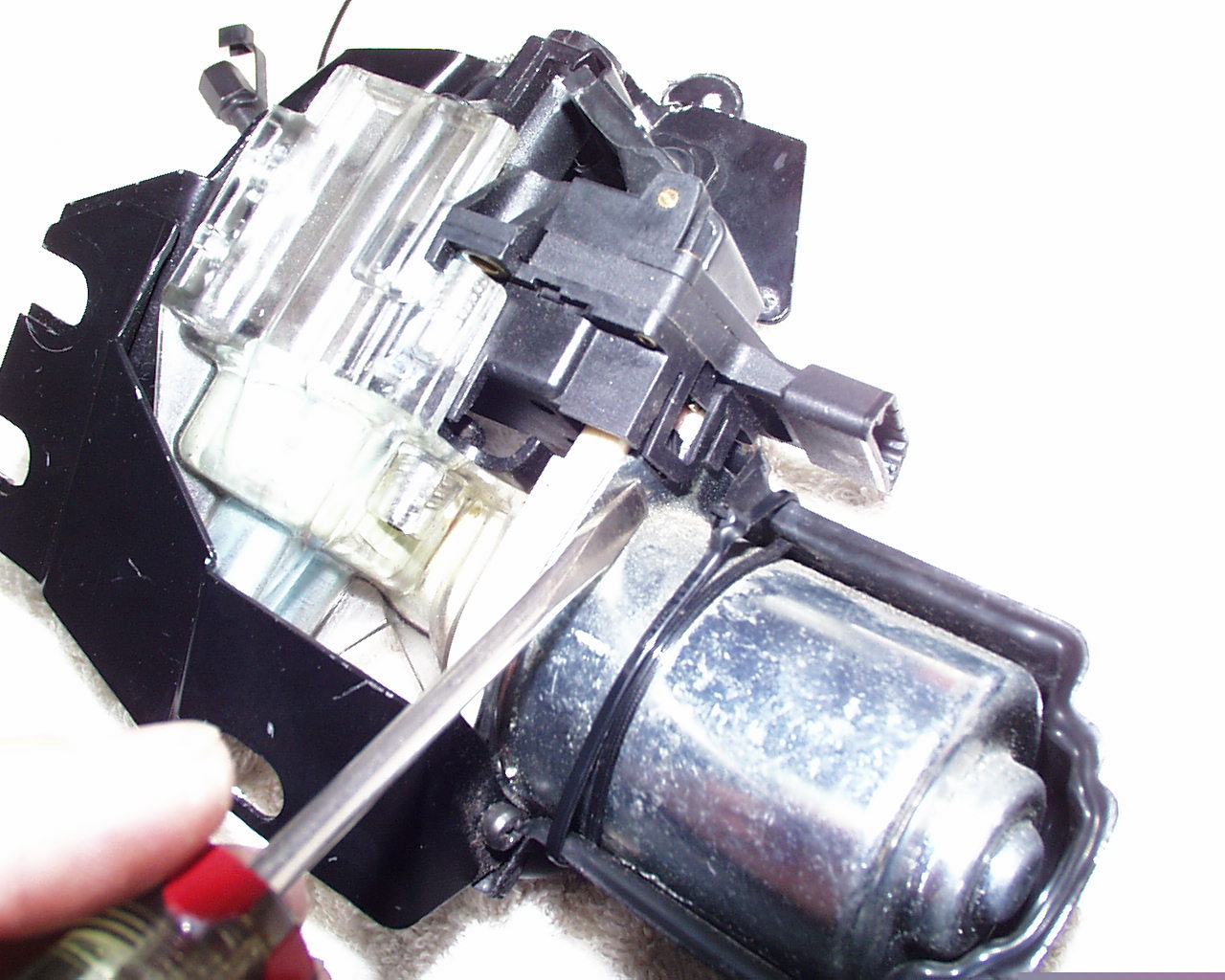
Removing T15 torx screw that holds Reversing Switch to assembly.

Prying up tab that holds Reversing switch to Electric Motor.
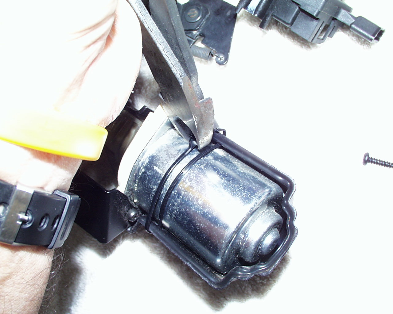
Cutting tie wrap that secures plastic cover over Electric Motor
DON'T LOOSEN THIS Phillips SCREW! Remove the one just touching heel of my hand. It secures
the rear alignment plate along with three 7mm silver bolts.

Next remove these three 7mm nuts holding alignment plate to rear of assembly.

Now remove the two T27 torx screws holding the latch assembly to the Clear Plastic
Housing.
Now you can lift the latch plate up and expose the top bearing, the gearnut and the
motor screw and all the bluish green lubricating grease.

Now you can pull the Clear Plastic Housing down and away from the white base of the motor. At this point all internal parts are accessible for service or replacement.
NOTE: Part no. 16629927 (Reversing Switch). Cost: Less than $20 from any GM dealer.
The replacement part will not include the metal extension
lever. With some skill one could either remove the rivets from the old switch and
carefully drill holes in the new RS and re-rivet the extension to the new switch or,
tap out the brass shaft holding the spring loaded lever and extension and swap it onto
the new switch.

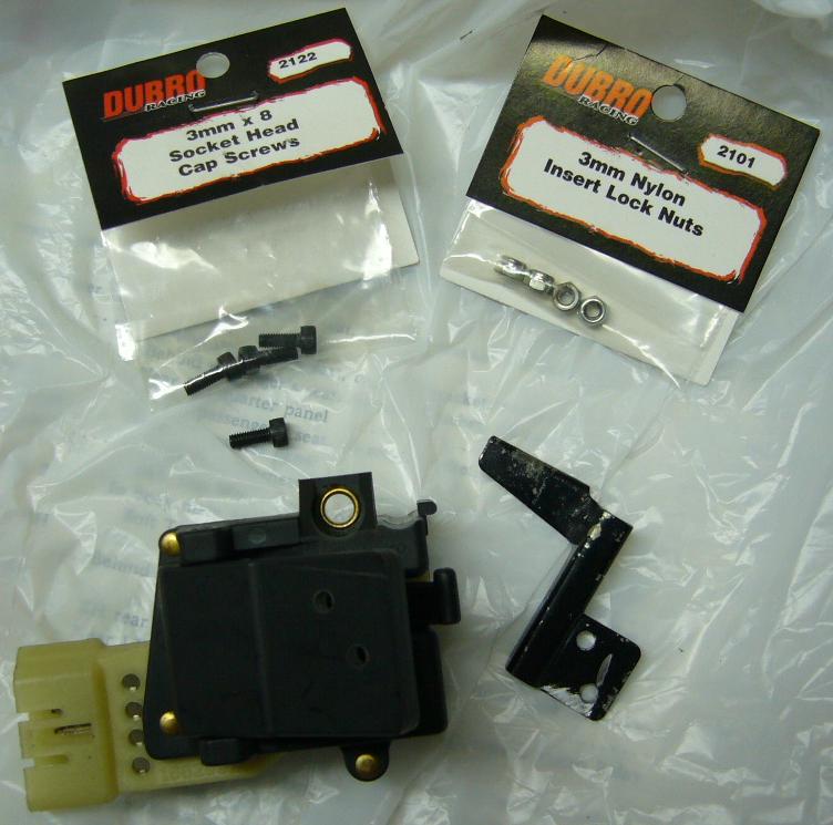
New pulldown switch after I used the lever for a template to drill the two holes in the switch lever.
Also shown are fasteners (acquired from hobby shop) required to attach the lever to the switch if you
decide not to use pop rivets.